

Tüm ürünler
-
Fark Basınç Göstergesi
-
dijital basınç göstergesi
-
Paslanmaz Çelik Basınç Göstergesi
-
Hassas Basınç Transmitteri
-
Programlanabilir Mantık Denetleyici
-
Şamandıra Seviye Şalteri
-
Pnömatik Valf Konumlandırıcı
-
Sıcaklık Verici Sensör
-
Hart Saha İletişimcisi
-
Selenoid vana
-
Kontrol Vanaları
-
Yüksek Doğruluk Debimetre
-
dalgıç su pompası
-
Basınç Transmitteri Manifoldu
-
Ultrasonik Seviye Ölçer
-
Gerilim Akım Güç Ölçer
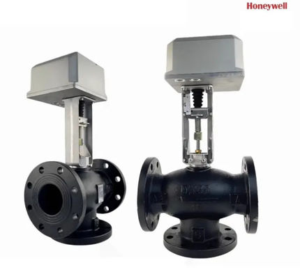
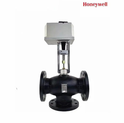
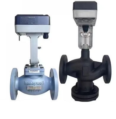
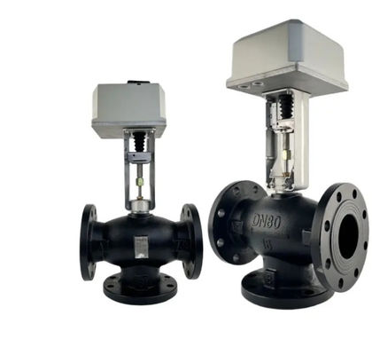
Honeywell ML7421 Proporsiyonel Entegre Kontrol Elektrik İki Yönlü Sıcaklık Valfi Dinamik Dengeleme Bakır Temas Malzemesi


| Menşe yeri | - |
|---|---|
| Marka adı | Honeywell |
| Sertifika | - |
| Model numarası | ML7421 |
| Min sipariş miktarı | 1 |
| Fiyat | USD200/PC |
| Ambalaj bilgileri | Orijinal |
| Teslim süresi | 2 hafta |
| Ödeme koşulları | L/C, D/A, D/P, T/T, Western Union, MoneyGram |
| Yetenek temini | 1000 |
Ürün ayrıntıları
| Ürün Adı | Sıcaklık Kontrol Vanası Dinamik Dengeleme Valfi | Paket | Orijinal karton paketi |
|---|---|---|---|
| Kalite | Yeni ve Orijinal | IP seviyesi | IP20 |
| İletişim malzemesi | Bakır | ||
| Vurgulamak | Elektrikli iki yönlü sıcaklık valfi,ML7421 Proporsiyonel Entegre Kontrol Valfı |
||
Ürün Açıklaması
Özellikler • Hızlı ve kolay montaj. • Ayrı bağlantı gerekmez. • ML7421A'da 3/4 inç (20 mm) darbe; ML7421B'de 1-1/2 inç (38 mm) darbe. • Düzenleme gerekmez.• Valfların doğru konumlandırılması. • Seçilebilir 0(2) 10 Vdc/0(4) 20 mA giriş sinyali. • Pozisyon geri bildirimi. • Güç sınırlayan uç anahtarları. • El operatörü. • Doğrudan veya ters hareket. • Senkron motor.• Korozyona dayanıklı tasarım. • Bakımsız. • Boru konektörünün kesilmesi.
Genel ML7421'de senkroniz motorun tahrik gücü, bir solucan vitesi iletimi kullanarak aktüatör sapının doğrusal hareketine dönüştürülür.Bir düğme tutturma klipi valf sapı aktüatör sapı bağlarİç kuvvet sensörü, yerleştirilmiş mikro anahtarları kullanarak, belirtilen sap kuvvetine ulaştığında aktüatörü kapatır.Manual Operasyon ML7421 manuel bir operatör düğmesi ile donatılmıştır (Şekil'e bakın). 7) Elektrik kesintisi durumunda valfi açmak veya kapatmak için. ML7421.'yi elle çalıştırmadan önce güç kaynağını kapatmak veya bağlantıyı kesmek için.El operatör düğmesini aşağıya itmek ve sapı aşağıya veya sapı yukarı hareket etmek için saat yönüne karşı sapı döndürmek. Eğer aktüatör otomatik kontrolüne döndürülürse, manuel operatör düğmesi otomatik olarak kilitlenir. NOT: Eğer manuel operatör düğmesi döndürülürken itilmezse,Güç geri alınmadan otomatik olarak çıkmadan önce sadece kısa bir mesafe döner.ÖNEMLİ: El ile çalıştırmak, motorun güç anahtarlarının nominal değerini aşarak aktüatör spindelini sıkıştırabilecek ve motoru durdurabilecek çok yüksek bir kapanma kuvveti sağlar.El valfi kapama işleminden sonra, bir dönüş yaparak makineyi serbest bırakın. Böylece makine güç yeniden başladığında otomatik olarak devre dışı kalır.Sinyal Girişi (+) Analog giriş sinyali (+) aralığı fabrikada 0 ila 10 Vdc'ye ayarlanmıştır.. W2 seçicisi fişinin konumunu değiştirmek, aralığı 2 ila 10 Vdc'ye ayarlar. W4 konumunu mA'ya değiştirmek (Şekil 8'e bakın) aralıkları 0 ((4) ila 20 mA'dır. Seçicisi fişleri W1, W2,W3 ve W4 PCB koruma levhasının arka tarafında yerleştirilmiştir.. Seçer fişlerinin konumu için Şekil 8'e bakın. Şekil 7. ML7421A,B manuel operatör düğmesi. Seçer fiş W1 kullanılarak Sinyal Giriş Arızası,İşaret arızası durumunda aktüatörü üç pozisyondan birine çalıştırmak için ayarlayabilirsiniz.: 1. 0% ∆ Aktüatör konumu 0 veya 2 Vdc sinyali ile eşleşir 2. 50% ∆ Aktüatör tabanı orta konumda 3. 100% ∆ Aktüatör konumu 10 Vdc sinyaliyle uyumludur NOT: W1 % 50 olarak fabrikada ayarlanmıştır.W4 mA pozisyonuna ayarlanmışsa, aktüatör her zaman % 0'da çalışır. W1 (W4) W3 W4 V![]()
![]()
![]()
![]()
Önerilen Ürünler